Wiring harness – inspect the vehicle wiring harness for damage prior to transmission installation.
Mounts – inspect all transmission and engine mounts.
Cooler Flush – make sure the cooler is properly flushed and that the cooler flow is sufficient for proper operation.
Bell housing Dowels (if applicable) – make sure the bellhousing dowels are properly installed and are protruding the proper amount.
Flexplates – remove flexplates to inspect inner and outer bolt holes for cracks.
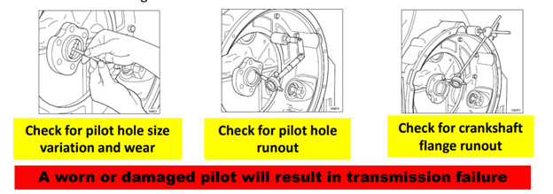
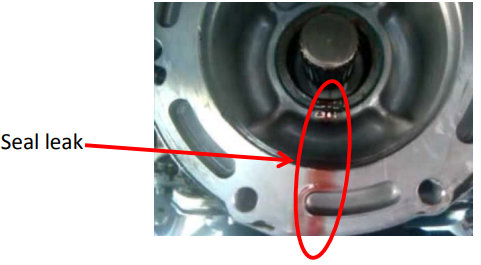
Crankshaft pilot/hub – inspect the crankshaft pilot/hub for damage and wear. The crankshaft pilot/hub and the converter pilot must not have excessive clearance otherwise wear and seal leakage issues will occur.
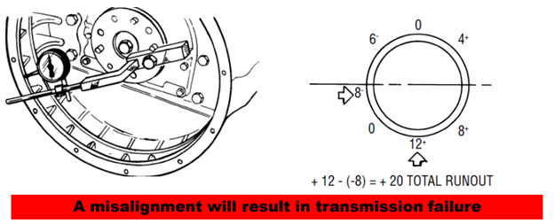
Engine Flywheel Housing Pilot Alignment
Dial indicate the pilot bore of engine flywheel housing. Secure dial indicator to engine flywheel with tapered point against housing pilot. Rotate the flywheel by hand. With chalk, mark the high and low points of the indicator as it is being rotated.
The total runout will be the difference between the highest plus and minus readings.
SAE maximum total runout for flywheel housing pilot is .008 on SAE #1 and SAE #2 housings. Example – In the example below the total run out equates to +.020 runout which exceeds the maximum tolerance. The engine bell housings need to be replaced.
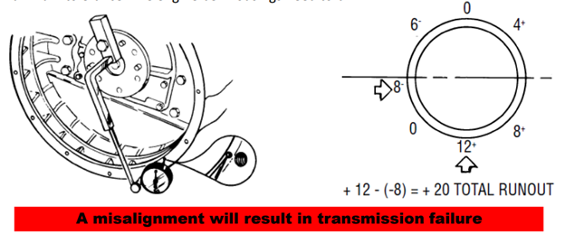
Engine Flywheel Housing Face Alignment
Dial indicate the face of the engine flywheel housing. With dial indicator secured to flywheel, move the tapered point to contact the face of flywheel housing. Mark high and low spots in same manor as previous step. Mark the high and low runout readings in clock positions in case it is necessary to reposition the flywheel housing.
The total runout will be the difference between the highest plus and minus readings.
SAE maximum total runout for flywheel face is .008 on SAE #1 and SAE #2 housings. Example – In the example below the total run out equates to +.020 runout which exceeds the maximum tolerance. The engine bell housings need to be repositioned
Converter – do not PULL the converter into the crankshaft pilot with the bolts. Alignment issues and seal leakage can result.
Converter – prior to tightening the bell housing bolts, make sure a space exists between the flexplate and the torque converter. If no space exists the converter is not fully seated into the pump gears and damage will occur.
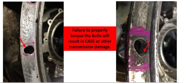
Torque – properly torque, to factory specifications, all of the bell housing and mount bolts with a torque wrench.
Driveline inspection – Inspect, lubricate and phase driveline.
Fluid – install the correct Allison Approved fluid for your application. Make sure the fluid level is correct using the internal Oil Level Sensor (OLS) through the keypad and factory installed dipstick. Over or under fill will damage the unit.
Shift Linkage (if applicable) – properly adjust the shift linkage using the factory approved procedures.
Diagnostic Trouble Codes (DTC’s) – Check, clear and address any DTC’s that may be set prior to operating the transmission. This includes ALL vehicle systems as the Transmission Control Module (TCM) communicates and utilizes information from several different control modules on the vehicle.
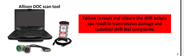
Adapts / Prognostics – Reset the shift adapts and prognostics.
Calibration – address any calibration updates for your application prior to operating the transmission.
PTO Interface
All automatic transmissions require a cooler.
The cooler acts as a “heat exchanger” to cool or heat the transmission fluid which helps maintain the proper fluid viscosity. Some applications utilize a stand alone external cooler (air to oil) while others have the cooler mounted within radiator. Some applications use a combination design that utilizes both a radiator and a remote cooler.
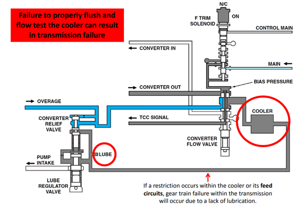
Transmission fluid within and automatic transmission is fed as follows: Pan-Filter-PumpTorque Converter-Cooler-Transmission Lubrication circuit.
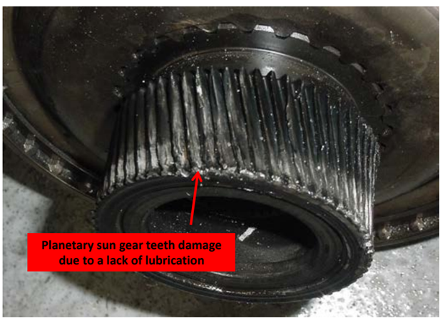
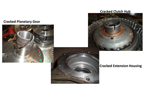
If a restriction occurs within the cooler or its feed circuits, gear train failure within the transmission will occur due to a lack of lubrication.
Restrictions within the cooler are typically due to failures from the previous torque converter or transmission.
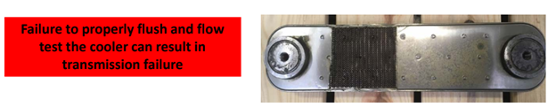
For this reason the cooler must be replaced or properly flushed to remove contamination and to assure correct cooler flow or damage to the “NEW” transmission will likely occur.
Contamination caused by not properly flushing or replacing the cooler.
Preventative Action
Flush the transmission cooler as part of the installation process.
Cooler Flow Volume Testing With A Hot Flush Machine
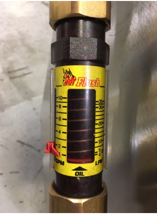
Flow Volume Testing Meter *part of the Hot Flush Machine
Flow volume testing allows one to determine if a restriction in the cooling system exists, even when the fluid appears to be clean
Hot Flush as well as some other flushing machine designs have a built in cooler flow device to measure cooler volume.
Cooler Flow Volume Testing With A Hot Flush Machine
With the “Return Cooler Line” disconnected, place the line into a clean bucket.
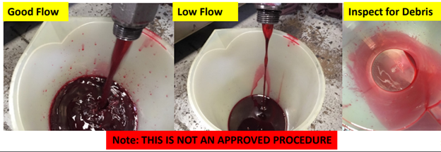
Overfill the transmission. Have an assistant help you with the following steps. a) While holding the line in the bucket, start the engine and monitor the fluid color and flow into the bucket. While keeping the unit full of oil note the fluid volume from the cooler. Note: Allison units pump large volumes of fluid through the cooler (several gallons per minute) so make sure you are prepared. Be sure to wear personal protection devices such as safety glasses and gloves.
If cooler volume is low, the cooler is restricted and will need to be replaced.
Once you have passed the volume check, dump the oil from the bucket and inspect the bottom of the bucket for debris. If excessive debris is found the cooler will need to be replaced. Good Flow Low Flow.
Vibration & Leaks
Vibrations do/can cause damage to the transmission as well as other vehicle components/systems. In some instances, on large trucks, the vibration cannot be felt by the driver.
A vibration is like a human finger print. Each vibration source will produce its own unique vibration frequency. Diagnostic equipment is available to help you isolate the EXACT severity and cause of the vibration.
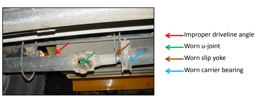
Typical sources of truck drive train vibrations include :
Worn components such as Mounts, U-Joints, Carrier Bearings, Springs
Driveshaft working angle or U-joint phase
Driveshaft runout or balance
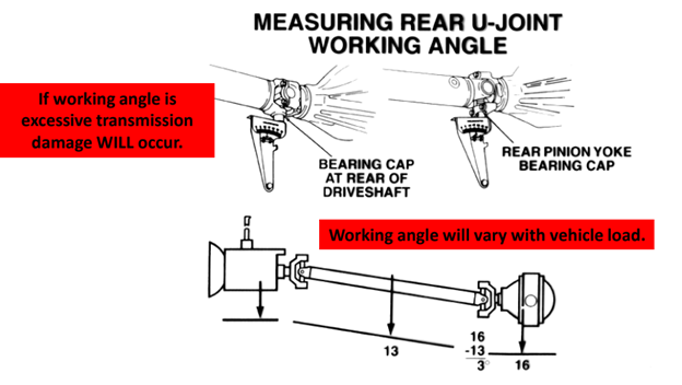
Measuring Working Angle
Air ride (if applicable) – The ride height has to be set to the vehicle manufacturer’s specification. Ensure leveling valve is working properly.
Non-air ride suspension – Working angle can be adjusted on most applications with the use of shims, torque arms or other means.
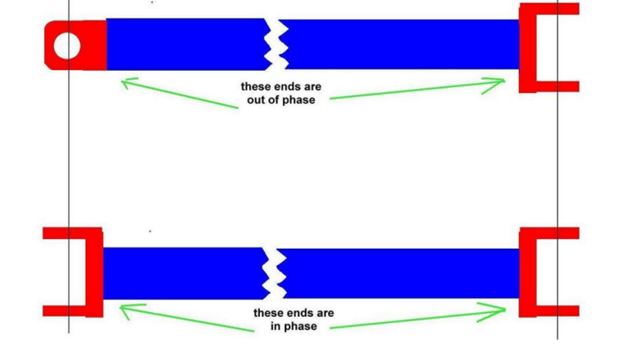
Driveshaft Phase
Each time the driveshaft rotates, the U-joints speed up/slow down on each end of the shaft twice per rotation. This can create a vibration.
The manufacture typically aligns the slip joint U-joint with the stationary joint which cancels the speed change eliminating the vibration.
On shafts without a master spline, to properly phase the shaft, align the joints on each end of the shaft as you install the end or slip yoke. Transmission seal leakage occurs when:
Input shaft seal
The torque converter was improperly installed.
The crankshaft pilot is worn allowing misalignment of the crankshaft to the converter pilot.
Bellhousing not properly torqued allowing the bellhousing bolts to loosen up.
Unit ran low on fluid leading to bushing damage due to lack of lube.
Lack of lube due to a restricted oil cooler.
Incorrect fluid
Output shaft seal
Improperly installed driveshaft.
Drive shaft vibration.
Loose or worn output yoke
Unit ran low on fluid leading to bushing damage due to a lack of lube.
Lack of lube due to restricted cooler.
Incorrect fluid.
Causes of Failure
Symptom
Vibration
Noise
Component failure
Leaks
Cause
Failure to inspect driveline and suspension components for systems deficiencies.
Preventative Action
Perform inspection prior to putting the vehicle in service.
Adaptive Learning
All Allison transmissions are equipped with a feature known as “adaptive learning”.
Adaptive learning allows the transmission to adjust for component wear and build variation.
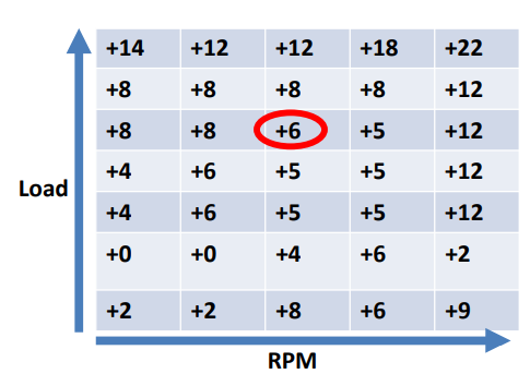
The adaptive learning system consists of a “block of cells” within the Transmission Control Module (TCM) memory.
The TCM transitions from cell to cell based on RPM and Engine load as well as other factors.
The values stored within the cells are based on the last time the transmission made that particular shift if it was considered an adaptable shift.
If the shift was aggressive the TCM will store a value that reduces pressure for the next shift to that gear. If the shift was too soft, the TCM will store a value that increases pressure for the next shift to that gear.
Shift Quality
In our example, the customer is operating the vehicle within the cell highlighted.
Based on the last adaptable shift the TCM will use a pressure offset of +6 PSI for that shift.
The TCM will then revaluate the shift quality and update the value stored in the cell if it needs more correction.
This means the value could increase or decrease based on the previous shift time.
NOTE: If DTC’s are set the TCM may freeze the shift adapt values. DTC’s MUST be corrected and cleared prior to attempting to relearn the transmission adapts.
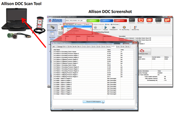
Since the transmission you are replacing likely has an issue, adaptive values (pressure offset values) will be stored in the TCM memory. The TCM does not know that you have installed a different transmission so it will command pressures based on the previous unit. This can lead to shift feel issues as well as it can significantly reduce the overall life of the unit.
Due to the adaptive values being stored in non-volatile memory, a scan tool such as Allison Doc will need to be used to reset the values to their baseline numbers.
Once the adaptive values have been reset, the vehicle will require an extended test drive to fully learn the adaptive values for the new/remanufactured transmission.
Adaptive learning values should be reset and relearned when any of the following occurs:
Transmission was replaced.
Transmission repairs were performed that could lead to shift quality issues such as overhaul or valve body replacement.
TCM was replaced.
TCM was recalibrated.
Adaptive Learning
Reset Not Performed
Symptom
Hard up-shifting and downshifting.
Shifting erratically.
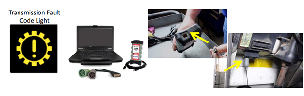
Transmission fault code. Transmission Fault light on.
Transmission Damage.
Cause
Failure to perform transmission “relearn” and reset all parameters on newly installed remanufactured transmission.
Preventative Action
Repair/clear all fault codes prior to putting the vehicle in service. Clear and relearn the adaptive values.
Adaptive Learning Prognostics
SOME Allison transmission applications are equipped with a software feature known as prognostics. Prognostics is a feature that monitors:
Fluid Life
Filter Life
Transmission Life
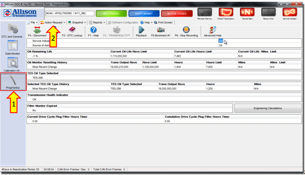
The system will alert you as to when the filter, fluid or transmission is at the end of its usable life. The TCM will display a message or trouble light in the shifter display area or such as:
Fluid Life %
Filters OK or replace filters
Transmission Health OK or Transmission health Low
Prognostic values must be cleared and reset if:
The fluid and/or filter was replaced.
The transmission was rebuilt or replaced.
Fluid, Filter and Transmission Health messages can be reset with the use of a scan tool such as Allison DOC or by using the +arrow, -arrow and the diagnostics button on the shifter pad.
To access the fluid/filter/transmission health stored information with Allison DOC click on the “Wrench” button
To clear and reset the prognostics values click on the “Action Request pull down menu.